New Work Bench

Recently I brought myself a BOSS MIG-186 some disposable Ar75%/CO25% for mild steel and Strait Ar Gas for Stainless. I've welded up a small movable welding bench with some 10mm plate for the table top.

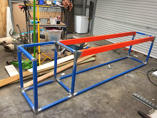
I wanted to make some more bench space so I've designed and fabricated a bench to go along the side-wall of the shed to marry up with the existing stainless bench and incorporate a sink. Eventually the plan is to put some cupboard doors on this to keep things looking a bit neater under the bench.

It's made of 40mm Square tube with a 2mm wall thickness and utilising two struts(orange) from some pallet racking for the under bench support, allowing for a 2600mm span. The steel was $160 the pallet racking pieces and sink where free.

Comments

Popular posts from this blog

Shortening the Diff

I have a Ford 8.8 inch diff from a EF/EB Ford Falcon with a Limited Slip Differential. I want to shorten it down to suit the 323. Due to the RX7 LCA in the front, the front tyres(205X50X15) now protrude from the front guards by 65mm. Making the overall front track width 1,675mm. With 225X50X15 tyres on the rear and the standard diff the rear is 1,610mm. Meaning that the rear track width is 32.5mm narrower on each side. To widen the rear when I shorten it, I'll make the rear axle 65mm wider than the standard rear axle. The standard 323 Diff width is 1,338mm and the Ford 8.8 is 1,547mm for a total difference of  209mm. So the Diff needs to be shortened by 209mm - 65 =  144mm or 72mm per side.

Suspension Design Solid works

To assist with integrating the Mazda RX7 S4 FC front suspension into my Mazda 323, I've decided to see if I can create a solid works model for the suspension and then one for the Mazda chassis to see what fabrication work is need to integrate it. Looking online into engineering tutorials I found a site called Grab CAD community and a tutorial on there around spring design in solid works which looks fairly strait forward. https://grabcad.com/tutorials/tutorial-how-to-model-a-suspension-spring-in-solidworks-and-show-design-intent The main issue I have is the Lower Control Arms (LCA's) are a rather complex shape and will require me to up-skill in SolidWorks to be able to reproduce them. I'm in the process of sandblasting the part and taking some better images from which to model it. *UPDATE -- 1FEB17 nearly finished sketching the LCA and spindles

Mazda_323

Mazda_323 The above link is for a suspension model I measured from the stock Mazda 323 suspension and setup in  the model creating tool at Racing ASP to assist in mapping the stock Roll Center and predicting the new roll center with the RX7 FC Suspension.